Mapping
A mapping represents an assessment of an area. Kryptos supports two types of mapping: Gas Mapping and Fire Mapping. Each mapping has its own grades and detector configurations, and its coverage is calculated independently.
A newly created area does not contain any mappings. Its Tree view initially displays only Decks. To create a mapping, enable it in Area Settings:
- Gas Mapping — enable the required gas component by ticking Enabled under Gas Mapping Parameters. Each gas component (Hydrocarbon HC, Toxic H2S, Toxic NH3, etc.) that is enabled will create a separate Gas Mapping for the respective component.
- Fire Mapping — tick Mapping Enabled under Fire Mapping Parameters.
WARNING
Enabling a mapping is not sufficient on its own. You must also click Apply Changes in Area Settings. Kryptos creates the mapping only when the changes are applied.
If you enable a mapping but close the panel without clicking Apply Changes, the mapping will not be created.
Once the settings are applied, the mapping appears in the area's Tree view, with Risk Grade and Configurations listed beneath it.
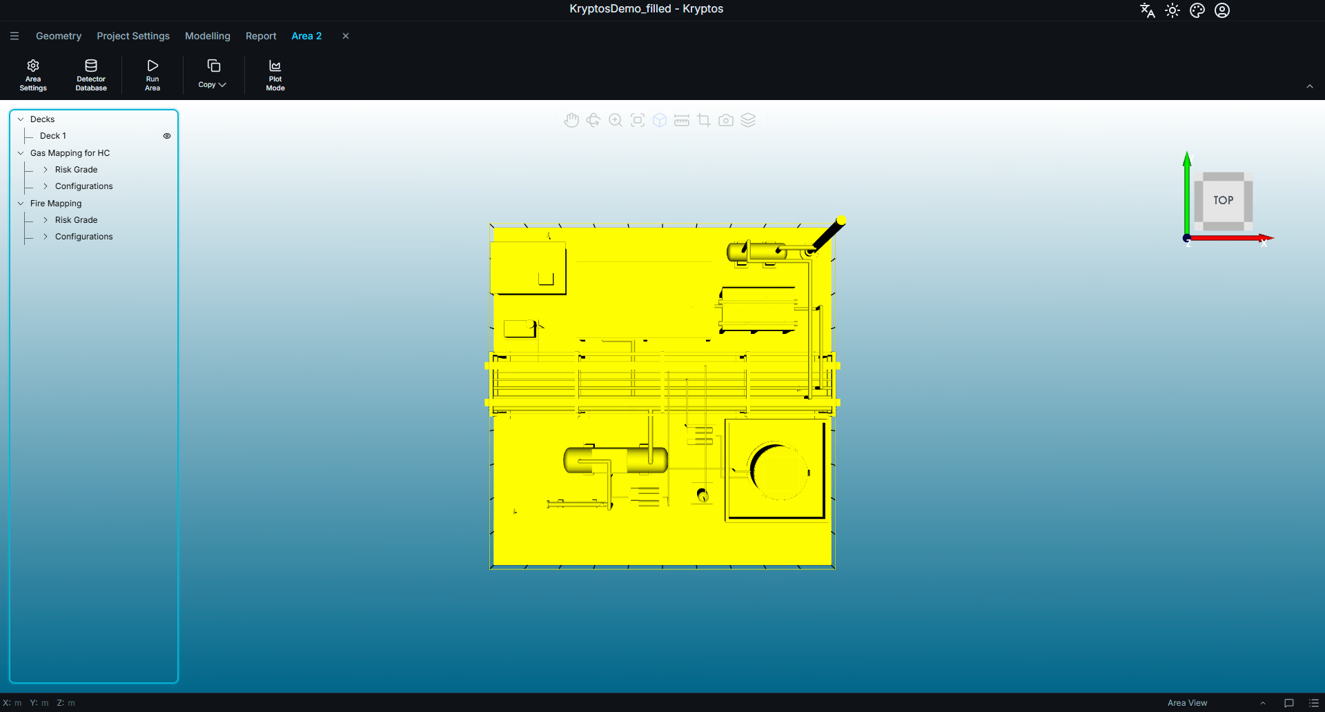
This page explains how to work with the contents of a mapping: Risk Grades, which define the risk volumes to be assessed for detector coverage, and Configurations, which contain the detector layouts used to protect those risk volumes.
TIP
The ribbon changes dynamically depending on the item selected in the Tree. If an action or button is not visible, check that you have selected the appropriate item in the Tree.
Risk Grades
A Risk Grade defines a risk volume within the plant for which detector coverage is to be assessed. You draw the volume in the 3D viewport and assign it a Grade Type configured in Project Settings. Kryptos then calculates and reports the detector coverage achieved within that risk volume.
Adding a Risk Grade
To add a risk grade, select Risk Grade under the required mapping in the area tree, then click Add Grade in the ribbon.
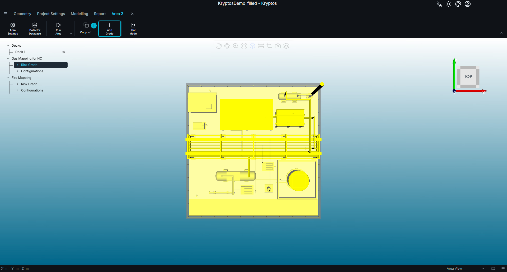
- Add Grade — opens the drawing panel, where you configure the new risk grade and define its geometry.
The drawing panel contains the settings required to create the risk grade.
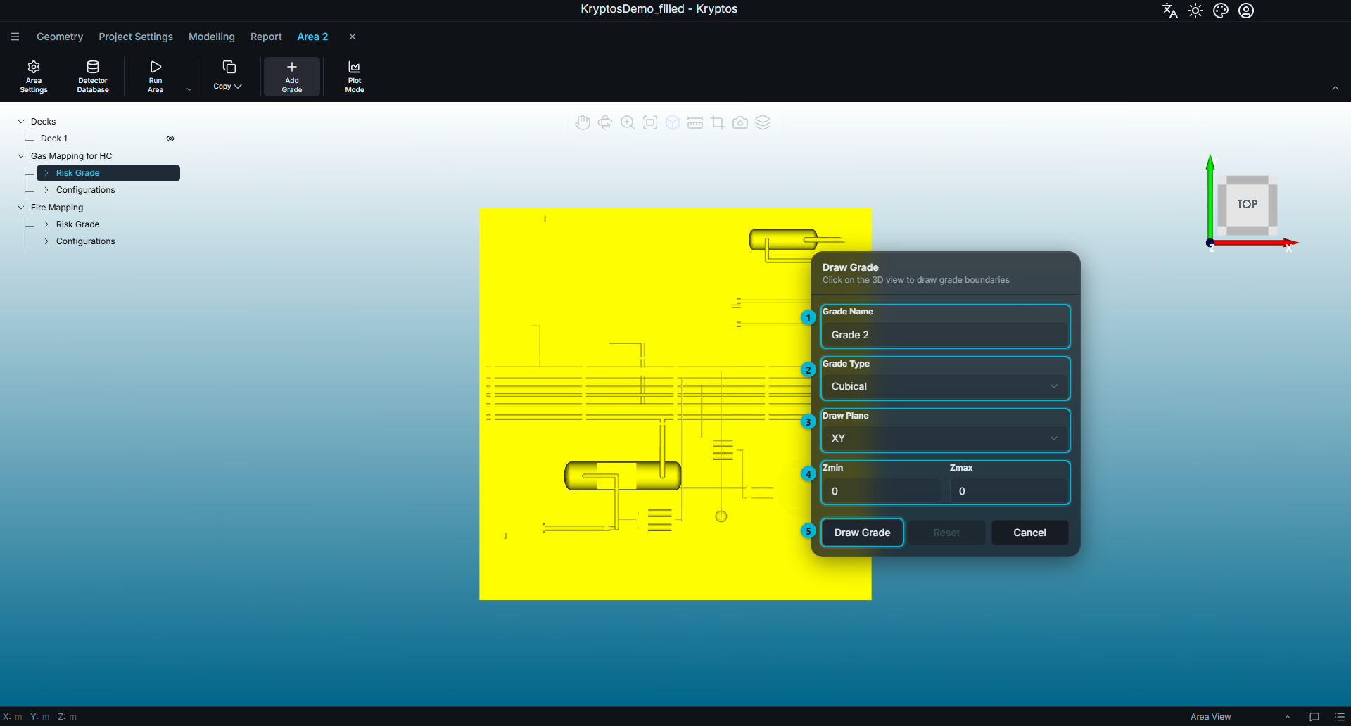
- Name — specifies the name assigned to the new risk grade in the area tree.
- Shape — defines the geometry of the risk grade. The available options are Cubical, Cylindrical and Polygonal.
- Draw Plane — specifies the plane on which the grade outline is drawn: XY, YZ or XZ.
- Extent — defines the minimum and maximum limits of the grade in the direction perpendicular to the selected draw plane. For example, when using the XY plane to draw the grade outline, the extent is along the Z-axis. The minimum value must be lower than the maximum value.
- Draw Grade — activates the drawing mode in the 3D viewport.
First, specify the name, shape, draw plane and extent. Then click Draw Grade and draw the outline in the 3D viewport. Once the outline is complete, the button changes to Complete. Click it to finish creating the grade.
While drawing, Reset and Cancel options are also available alongside Complete. If the drawing panel obstructs the part of the model you need to work on, you can move it by dragging its header.
WARNING
You cannot start drawing a grade until a valid extent has been specified. Both extent values are initially set to 0. The minimum must be lower than the maximum.
If the extent values are invalid, Kryptos displays the message "Min must be less than max", and the drawing operation will not start.
WARNING
The ribbon and area tree are locked while you are in drawing mode. Click Complete to finish the operation, or Cancel to exit without saving the grade.
The Three Shapes
Kryptos supports three geometry types for defining Risk Grades - Cubical, Cylindrical and Polygoanal.
Cubical — move the cursor in the 3D viewport to draw a rectangle representing the grade's outline. Once drawn, white handles appear on the shape, allowing you to adjust its dimensions.
Cylindrical — move the cursor in the 3D viewport to draw a circle. The handle at the centre allows you to reposition the circle, while the handle on its circumference adjusts the radius. The radius is displayed along the line connecting the two handles as you drag.
Polygonal — click at successive locations in the 3D viewport to place vertices and define a custom outline.
The following shortcuts are additionally available while drawing a polygon:
| Input | Effect |
|---|---|
| Middle Mouse Button | Switches between straight line segments and a smooth curve. This helps Kryptos determine how to connect two points in the polygon. |
| Delete | Removes the last point placed. |
Regardless of the selected shape, the outline is drawn on the selected draw plane. Kryptos then extrudes the outline shape between the specified minimum and maximum extent values to create a three-dimensional risk volume.
TIP
Reset clears the current drawing and allows you to start again using the same shape and draw plane. This is quicker than cancelling the operation and reopening the drawing panel.
Choosing the Risk Grade
Drawing a grade defines its geometry and volume. The risk grade it represents is assigned separately.
To assign a risk grade, select the grade in the area tree. Its properties panel appears in the viewport.
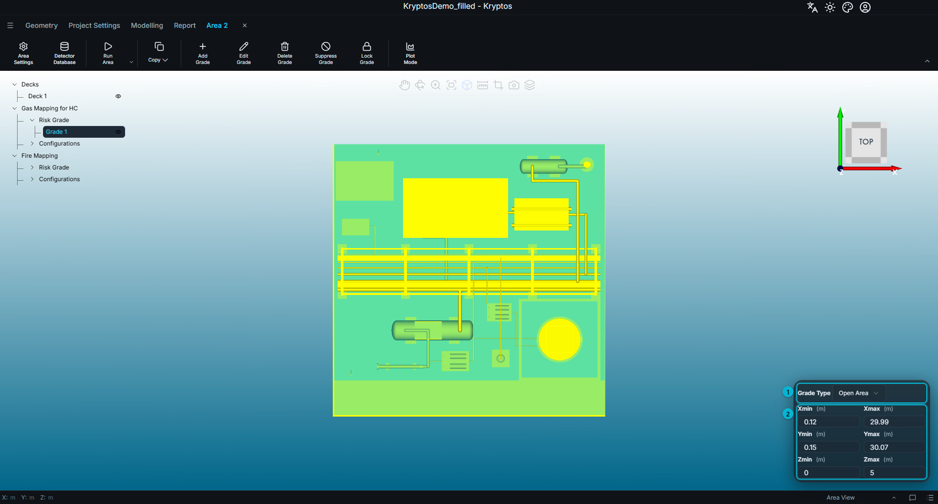
The panel contains two main sections:
- Grade Type — specifies the risk grade assigned to the volume. The dropdown lists the risk grade types enabled for the current mapping in Project Settings → Risk Grade Types.
- Coordinates — defines the grade's dimensions and position. For a cubical grade, the minimum and maximum coordinates are specified along each axis. For a cylindrical grade, the centre coordinates, extent and radius are specified.
Changes to these values are saved automatically when you move out of the corresponding input field. The grade geometry is also updated accordingly.
Editing a Grade
There are two ways to modify an existing Risk Grade, depending on whether you need to change its dimensions numerically or reshape it visually.
Edit the coordinates — use the grade properties panel to enter precise values. For a cubical grade, you can specify the exact minimum and maximum coordinates along each axis. For a cylindrical grade, you can modify its centre, extent and radius.
Edit Grade — click this option in the ribbon to reopen the drawing mode. You can then modify the grade's shape directly in the 3D viewport. Click Complete to save the changes.
WARNING
When editing an existing grade, Reset does not restore the original grade geometry. It clears the current shape and allows you to draw a new one from scratch.
If you want to discard your changes and retain the original grade, click Cancel instead.
Suppressing, Locking and Deleting a Risk Grade
Three ribbon actions allow you to manage an existing grade:
- Suppress — excludes the Risk Grade from coverage calculations without deleting it. This is useful when you want to temporarily assess the contribution of other grades. Click Unsuppress to include the Risk Grade in subsequent calculations again.
- Lock — makes the Risk Grade read-only, preventing accidental modifications or deletion. Click the option again to unlock it.
- Delete — permanently removes the grade from the mapping.
Configurations
A configuration is a particular arrangement of detectors within an area. A mapping can contain multiple configurations, allowing you to create and compare different detector layouts.
Each configuration is calculated independently, making it possible to evaluate alternative detector arrangements without modifying the original layout.
Adding a Configuration
Select Configurations under the required mapping in the area Tree view, then click Add Configuration in the ribbon.
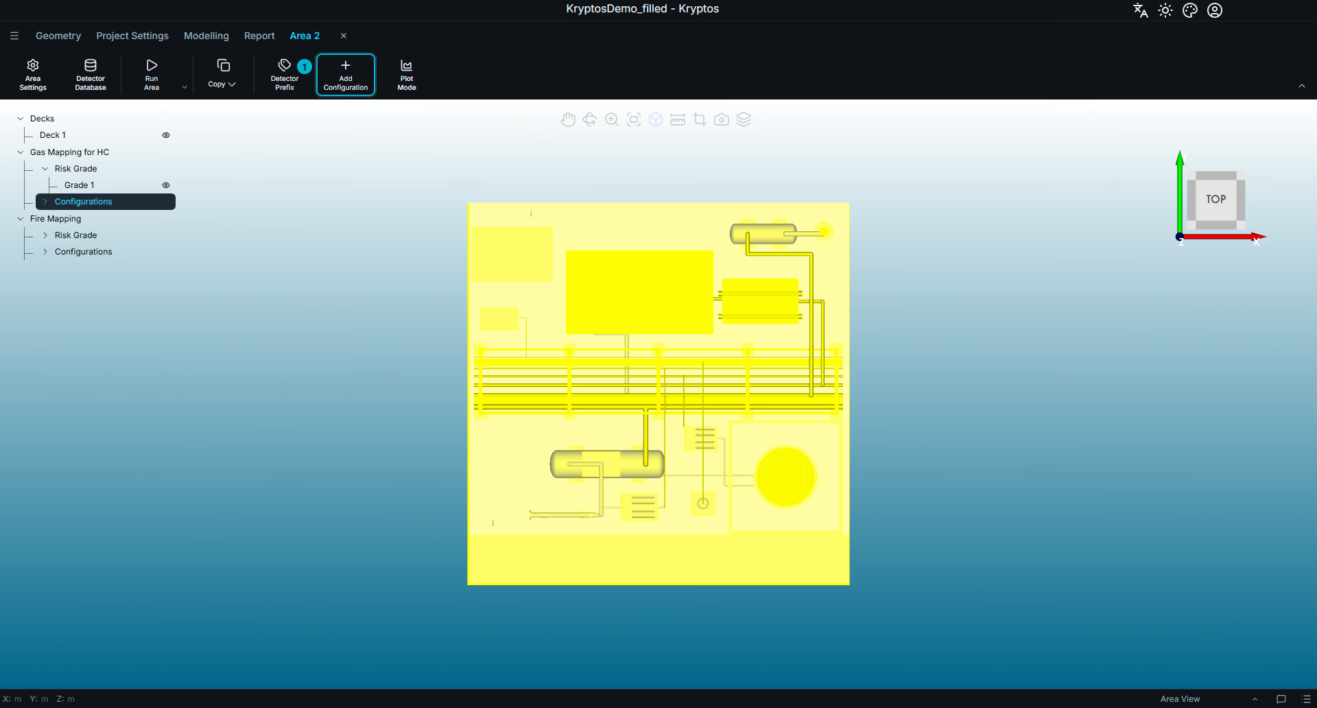
- Add Configuration — creates a new, empty detector configuration.
Just like Risk Grades, configurations can also be edited, suppressed, locked and deleted using the ribbon actions. Suppressing a configuration excludes it from the calculation without deleting its contents.
Preliminary and Final Configurations
Two configurations in each mapping can be designated for inclusion in the project summary and report:
- Preliminary — represents the initial or proposed detector layout.
- Final — represents the optimised detector layout selected for delivery to the client.
To designate a configuration as Preliminary or Final, select it in the area tree and click Set Configuration in the ribbon. Choose either Set Config as Prelim or Set Config as Final.
WARNING
Only the configurations designated as Preliminary and Final are included in the summary and report. All other configurations are treated as working alternatives. You can calculate and review them in Kryptos, but they will not appear in the report.
A configuration designated as Preliminary or Final cannot be deleted or suppressed while it retains that designation. Remove the designation first if you need to delete or suppress the configuration.
Adding Detectors
To add detectors, first select the configuration in which they are to be placed.
The Add button in the ribbon becomes a dropdown containing the Add Detector option.
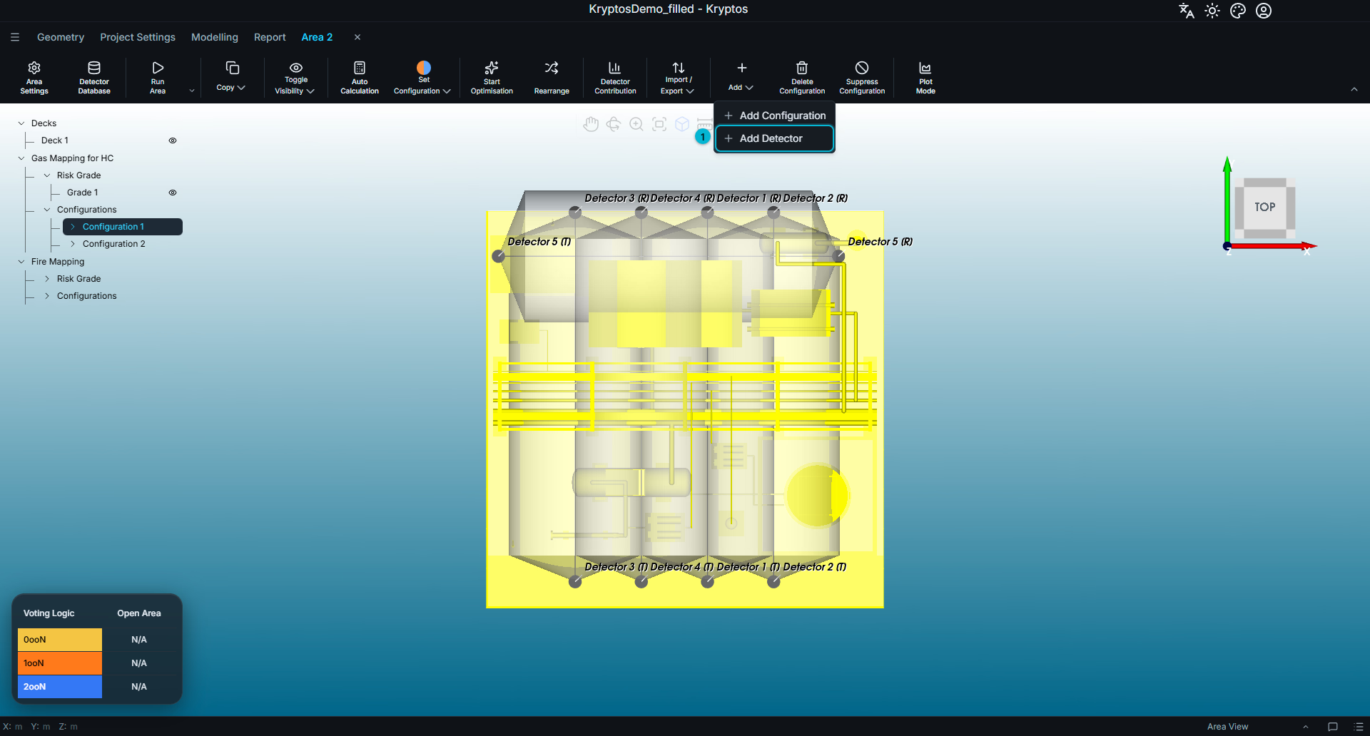
- Add Detector — adds a new detector to the selected configuration and activates the placement operation.
TIP
The same Add dropdown also provides the Add Configuration option. You can create another configuration directly from here without having to select the Configurations item in the area tree.
To place a new detector, click the desired location in the 3D viewport. The detector is created at that location, and its coordinates are populated and saved automatically.
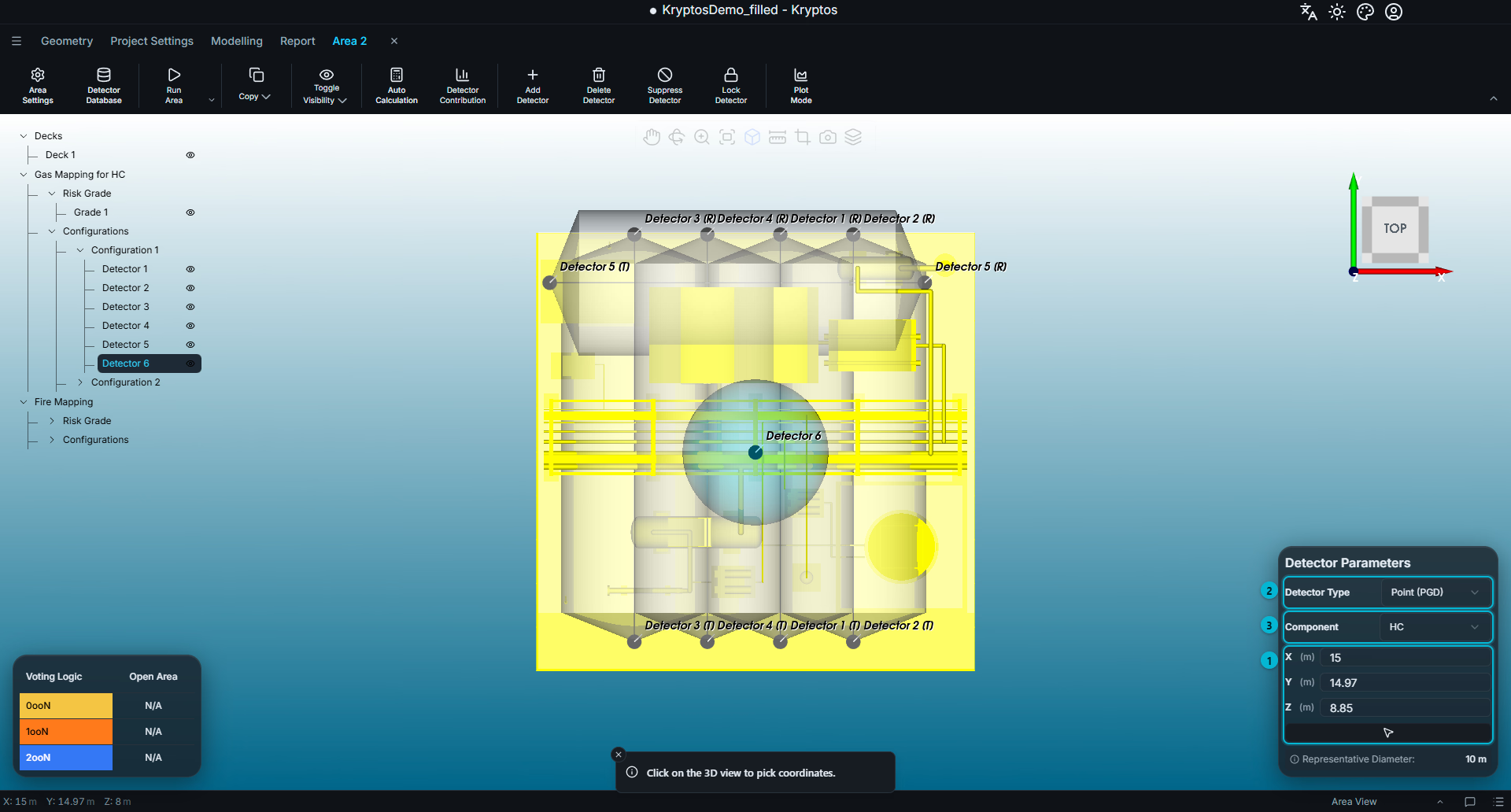
The detector properties panel contains the following fields:
- Location — specifies the detector's X, Y and Z coordinates. You can enter the coordinates manually or click the pick button and select a location directly in the 3D viewport.
- Type — applicable to gas detectors. A Point Gas Detector (PGD) is positioned at a single location, whereas an Open Path Gas Detector (OPGD) consists of a Transmitter and a Receiver with an Infra Red beam running between them. Consequently, an OPGD detector has two sets of coordinates - one for Transmitter and one for Receiver.
- Component — specifies the gas component that the detector is intended to detect. Only components enabled in Project Settings are available for selection.
- Orientation — applicable to fire detectors only. Horizontal Angle specifies the direction in which the detector faces, while Vertical Tilt specifies its upward or downward inclination. Both values are expressed in degrees.
Changes to detector properties are saved automatically when you move out of the corresponding input field.
The panel also displays the detector's representative diameter (for gas detectors) or representative range (for fire detectors). The representative value is taken from the Detector Rep configured previously in Area Settings. It affects only the detector's visual representation and is not used in the coverage calculation.
TIP
You can define a naming convention for newly added detectors using Detector Prefix under the Configurations item in the area tree.
For example, if the prefix is set to FX101_, newly added detectors are automatically named FX101_1, FX101_2, FX101_3, and so on.
This is particularly useful when placing a large number of detectors, as it avoids having to rename each detector individually.
Suppressing, Locking and Deleting Detectors
Detectors can be managed in the same way as risk grades:
- Suppress — excludes the detector from the coverage calculation without removing it from the configuration.
- Lock — makes the detector read-only, preventing accidental changes or deletion.
- Delete — permanently removes the detector from the configuration.
TIP
To evaluate the contribution of an individual detector, suppress it and run the coverage calculation again. Comparing the results before and after suppression helps you understand how much that detector contributes to the overall coverage.
TIP
Locking detectors in a configuration is particularly useful in the following situations:
Mandatory detector locations
The project philosophy may require detectors to be installed at specific locations, regardless of the outcome of the optimisation. In such cases, place the detectors at the mandatory locations and lock them.
Any subsequent optimisation run will account for these locked detectors when calculating coverage and determining the placement of additional detectors. This ensures that the mandatory detectors are retained while Kryptos optimises the remaining detector layout.
Taking cross-credit for gas detectors
In some projects, the design philosophy may allow coverage provided by detectors assigned to one gas component to be credited towards another.
For example, consider an area with an existing optimised layout for Hydrocarbon (HC) gas mapping. The same area may also contain a toxic gas component, such as H₂S, in a mixed HC–H₂S stream. If an HC leak is expected to trigger an alarm before the H₂S concentration reaches its alarm threshold, the HC detectors may also provide an opportunity to detect the release before it becomes a toxic hazard.
In such cases, you can copy the optimised HC detector layout into the H₂S mapping configuration and lock those detectors. When you subsequently run gas optimisation for the H₂S configuration, Kryptos accounts for the coverage already provided by the locked HC detectors. The optimiser can then focus on placing additional H₂S detectors only where required to meet the specified coverage targets, potentially reducing the number of additional detectors needed.
Caveat: Cross-crediting coverage between gas components must be justified by the project's design philosophy and supported by the relevant gas release characteristics, detector response, alarm thresholds and applicable design criteria. It should not be assumed that HC detectors can automatically be credited towards H₂S detection or vice versa in every application.
Related
- Area Settings — configure the settings that determine which mappings are available in an area.
- Running Calculations — calculate coverage once your risk grades and detector configurations are in place.
- Project Settings — configure the risk grade types available to the project.