Areas
An area is the zone being mapped: a bounded volume within the plant model, with its own risk grades, detector configurations, and coverage results. All calculations performed by Kryptos are carried out on an area-by-area basis.
This page covers how to create an area, select the detector models available to the project, and configure the area's settings.
Create an Area
Areas are created from the Modelling tab.
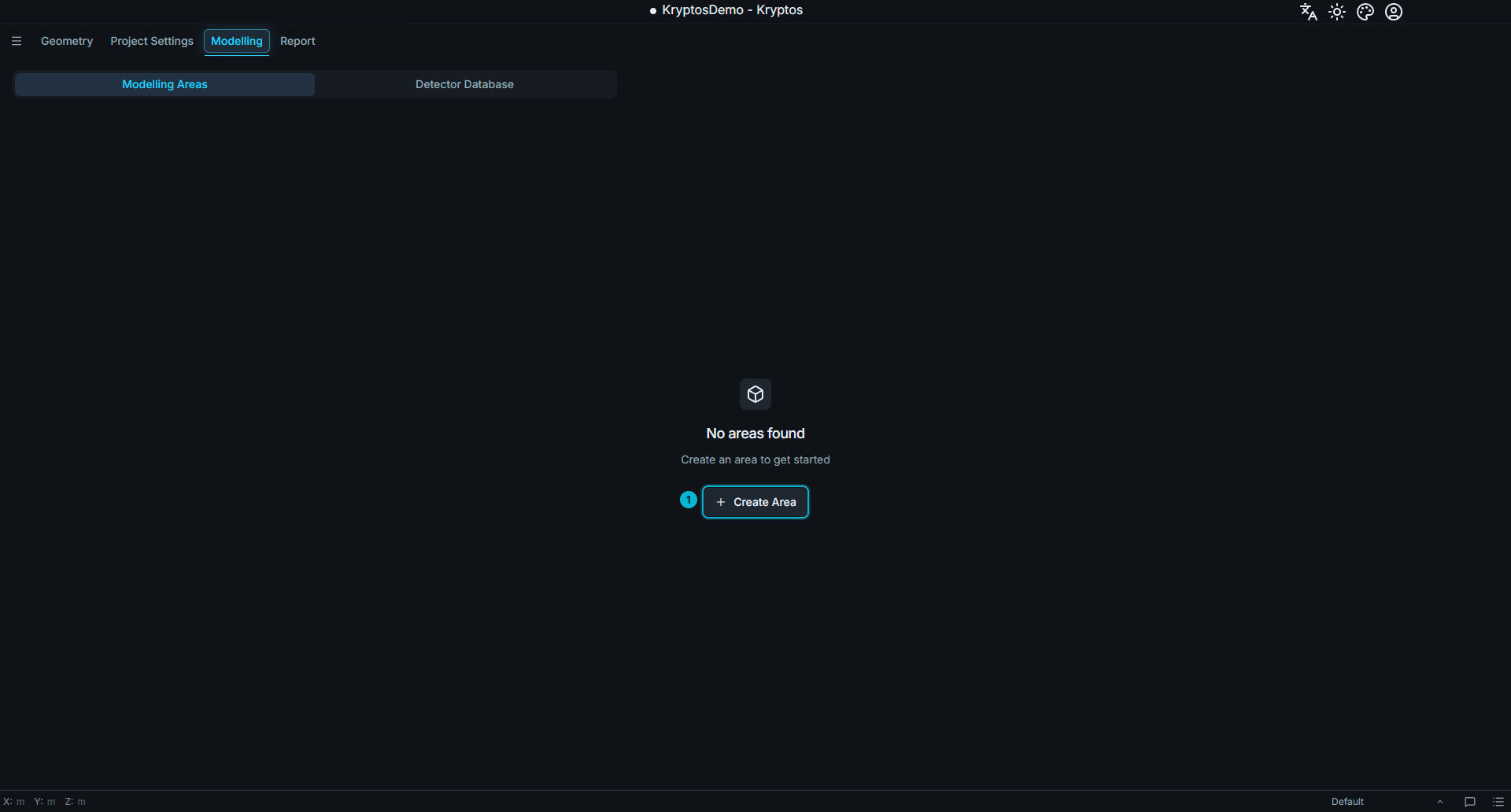
- Create Area — creates a new area in the project and opens it as a separate tab.
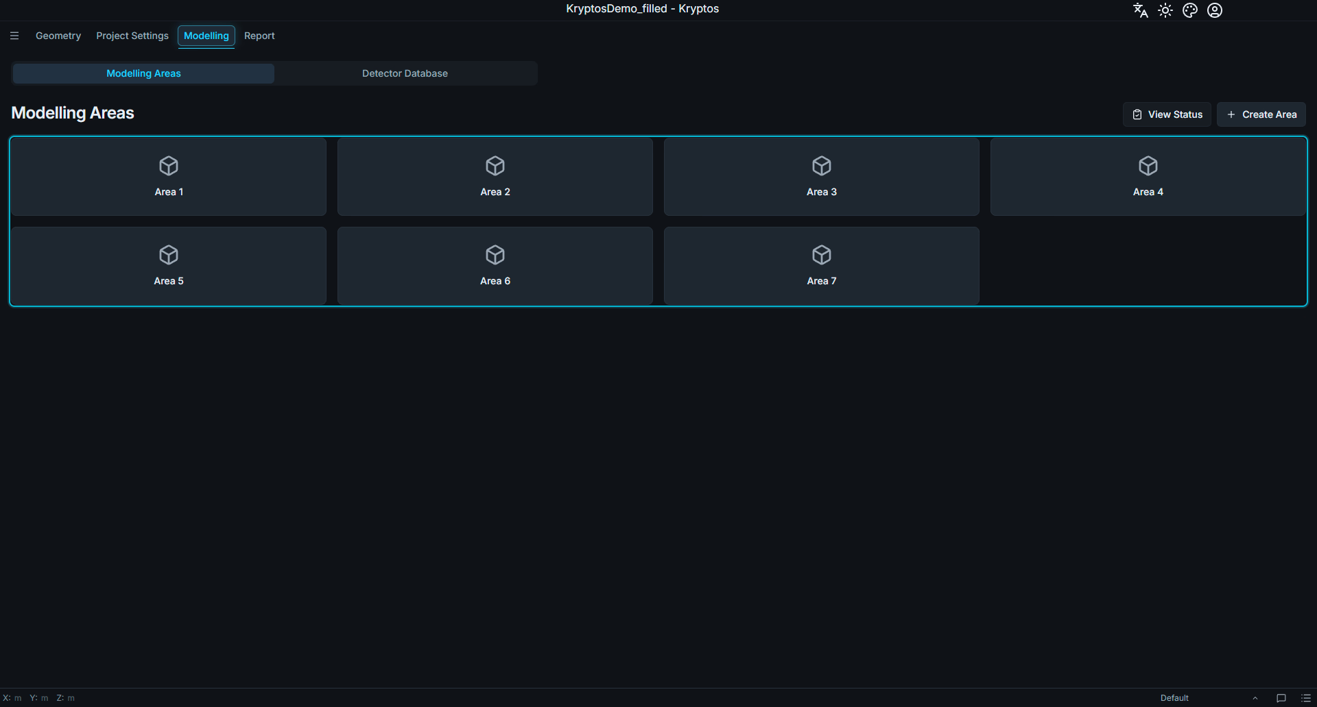
When one or more areas are created, each area is displayed as a card on the Modelling tab. Clicking a card opens the corresponding area in its own tab. Multiple area tabs can be opened simultaneously.
Area Settings
Area Settings in the area ribbon opens the settings for the active area. The settings are organised into four sections:
- Area Parameters
- Gas Mapping Parameters
- Fire Mapping Parameters
- Fire Detection Method
Area Parameters
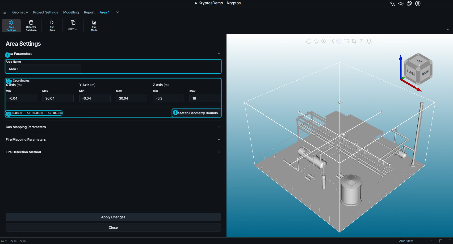
Name — the name assigned to the area. You may change the name to something that suits the project. For e.g., FZ 1 or Fire Zone 1, etc.
Coordinates — the minimum and maximum bounds of the area along each axis. It is recommended to keep each area to approximately one fire zone where practical. Smaller areas reduce the amount of geometry that Kryptos needs to process, making the model more responsive and improving the speed of coverage calculations and plot visualisation.
TIP
Avoid making an area unnecessarily large, particularly along an axis where the plant geometry occupies only a small portion of the available space. For example, if the highest point of the plant is only 10 m above the reference level, but the +Z boundary of the area is set to 100 m, the area extends far beyond the actual plant geometry. The grades and coverage plots will then occupy only a small portion of the available area, making them appear very small in the 3D viewport requiring you to zoom in repeatedly to examine the results.
Keeping the area boundaries reasonably close to the actual plant geometry ensures that the grades and coverage plots are always displayed at a useful scale and makes the model, risk grades, detector FOIs and coverage plots easier to visualise and work with.
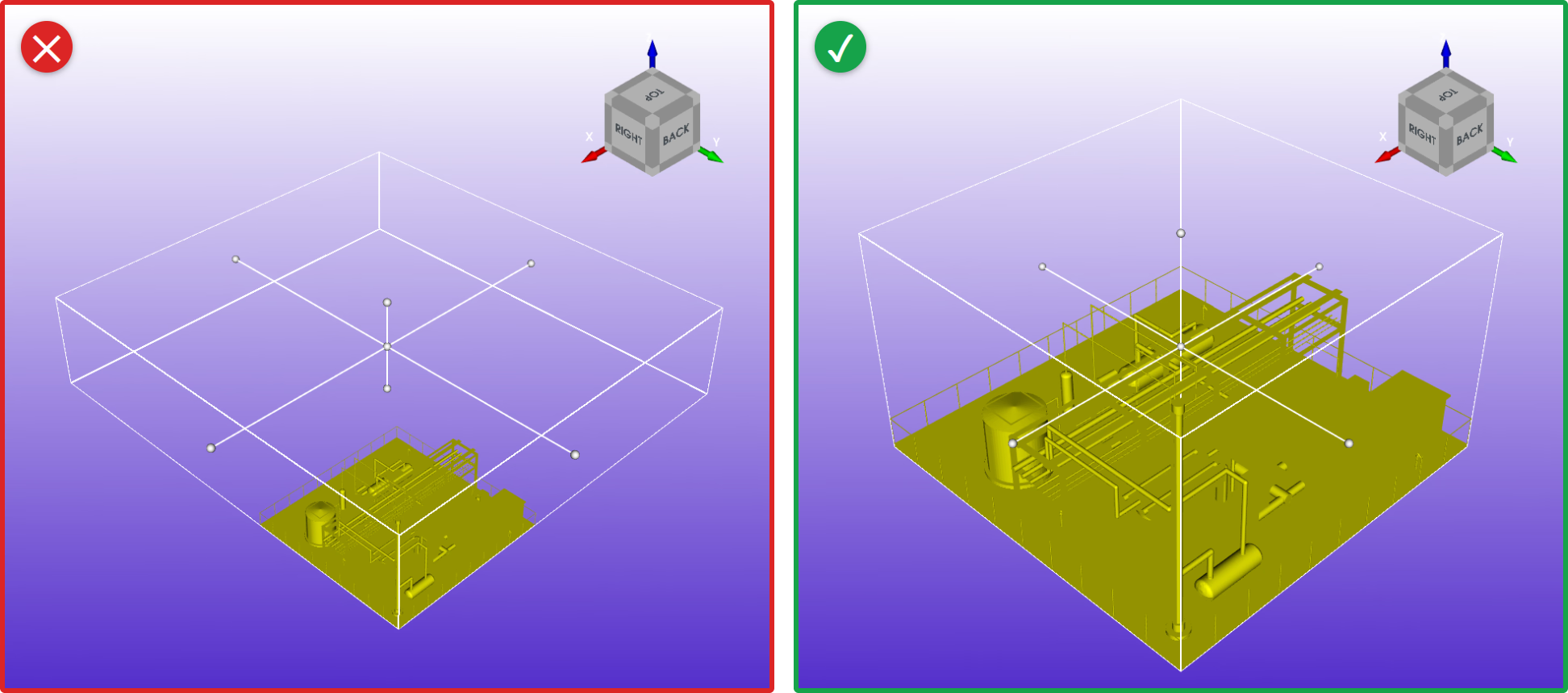
The area on the left (red cross) reaches far above the plant, which wastes space and slows down calculations. The area on the right (green tick) stays close to the geometry.
Reset to geometry bounds — resets the area coordinates to match the entire bounds (full extent) of the geometry imported into the project.
Area Size (ΔX, ΔY, ΔZ) — the size of the area along each axis, which is the maximum minus the minimum. It updates as you change the coordinates.
You can define the area bounds in either of two ways:
- Enter the coordinates directly.
- Resize the area interactively in the 3D viewport.
In the 3D viewport, the area is displayed as a box outline with white spherical handles. Dragging a handle resizes the area along the corresponding axis.
TIP
If you lose track of the area's position or dimensions, click Reset to geometry bounds to return it to the original bounds of the imported geometry.
Gas Mapping Parameters
This section allows to you activate or deactivate any gas component applicable for the current area from the list of those selected in the Project Settings. See Gas Component & Optimisation Settings for how to add components.
INFO
A project may have multiple areas with different gas components to be detected in each area. For e.g., Area 1 may require only Hydrocarbon (HC) gas mapping, Area 2 may only require H2S gas mapping, while Area 3 may need both HC and H2S mapping. So you can select all the gas components to be mapped for the entire project in the Project Settings tab, while you only activate only HC component in Area 1, only H2S in Area 2 and both HC and H2S in Area 3.
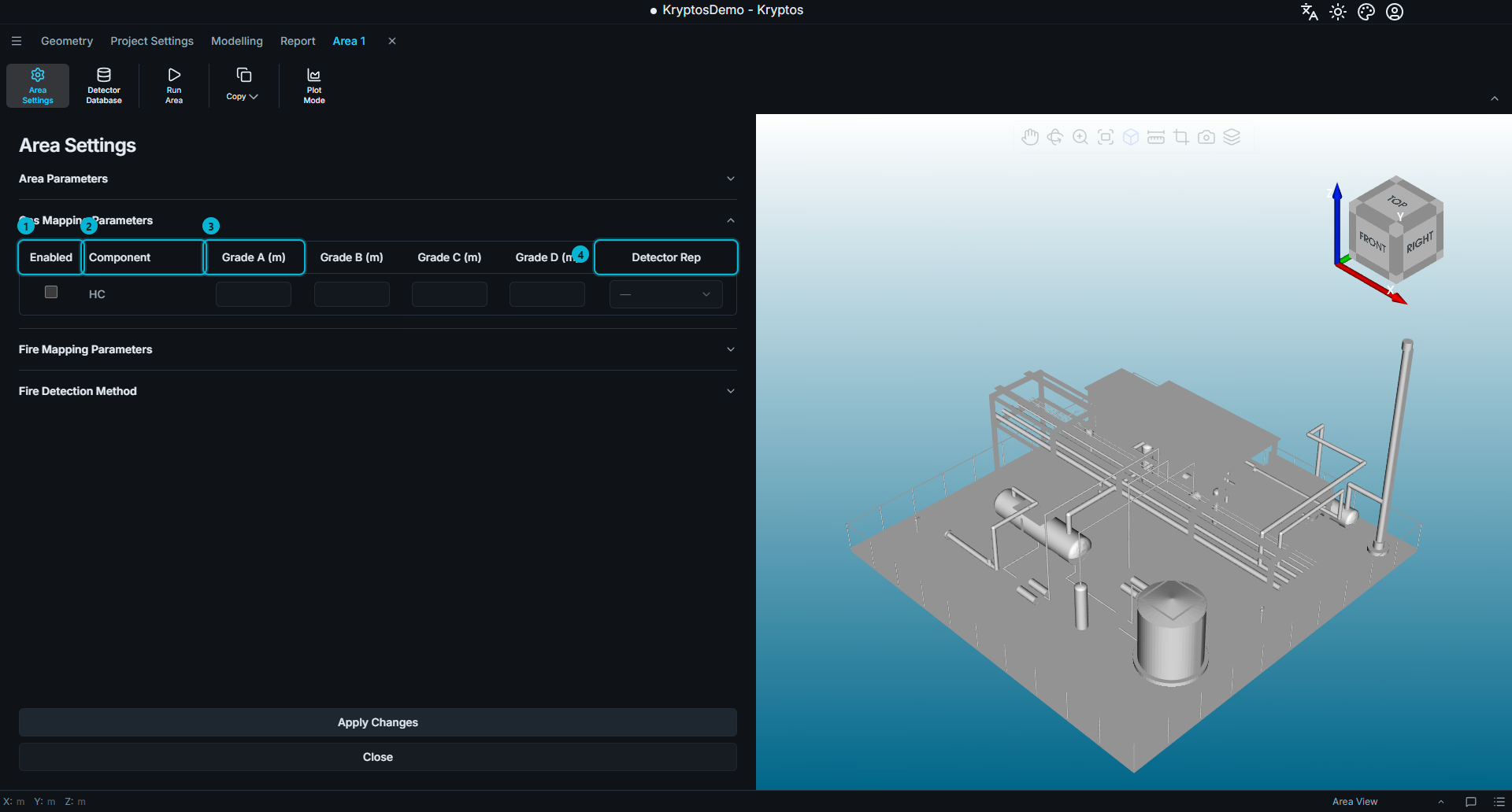
Enabled — activates the gas component(s) for mapping in the current area.
Component — identifies the gas component(s) that are available to be enabled or disabled. Note that only the gas components enabled in Project Settings appear here.
Risk Grade Diameters — specifies the cloud diameter associated with each risk grade for the selected gas component. For each enabled component, enter the cloud diameter corresponding to each risk grade. (Use project's units here.) The cloud diameter defines the size of the gas cloud that can be detected by a detector in that risk grade.
Detector Rep — specifies which risk grade's diameter is used to represent gas detectors' Field of Influence (FOI) for the corresponding gas component in the 3D viewport. This setting affects the visual representation only and does not affect the calculation for the different risk grades.
TIP
If no Detector Rep is selected, Kryptos uses the diameter of the first grade. If that value is also blank, detectors are displayed with a default diameter of 10 project units.
If a detector appears unusually large or small in the viewport, check that the appropriate grade diameter has been entered correctly.
Fire Mapping Parameters
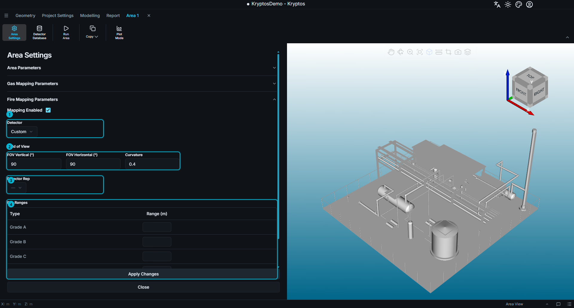
Detector — the fire detector model used by the area. The Detector dropdown lists the fire detector models selected in the Detector Database, together with the Custom option.
Field of View (FOV) — defines the vertical FOV, horizontal FOV, and curvature.
Detector Rep — specifies which risk grade's range is used to represent fire detectors' Field of Influence (FOI) in the 3D viewport. This setting affects the visual representation only and does not affect the calculation for the different risk grades.
Fire Ranges — defines the detection range for each risk grade and alarm level.
TIP
Selecting a detector model from the database automatically populates the associated detector parameters, including horizontal FOV, vertical FOV, curvature, and detection ranges.
Select Custom when you want to enter these parameters manually.
Detector Rep for Fire Detectors works in the same way as it does for gas detectors, except that it uses a risk grade's detection range rather than a cloud diameter. If no Detector Rep is selected, Kryptos uses the range of the first risk grade. If that value is also blank, detectors are displayed with a default range of 10 project units.
If a detector appears unusually large or small in the viewport, check that the appropriate risk grade range has been entered correctly.
For an explanation of these parameters, see Fire Detectors.
Fire Detection Method
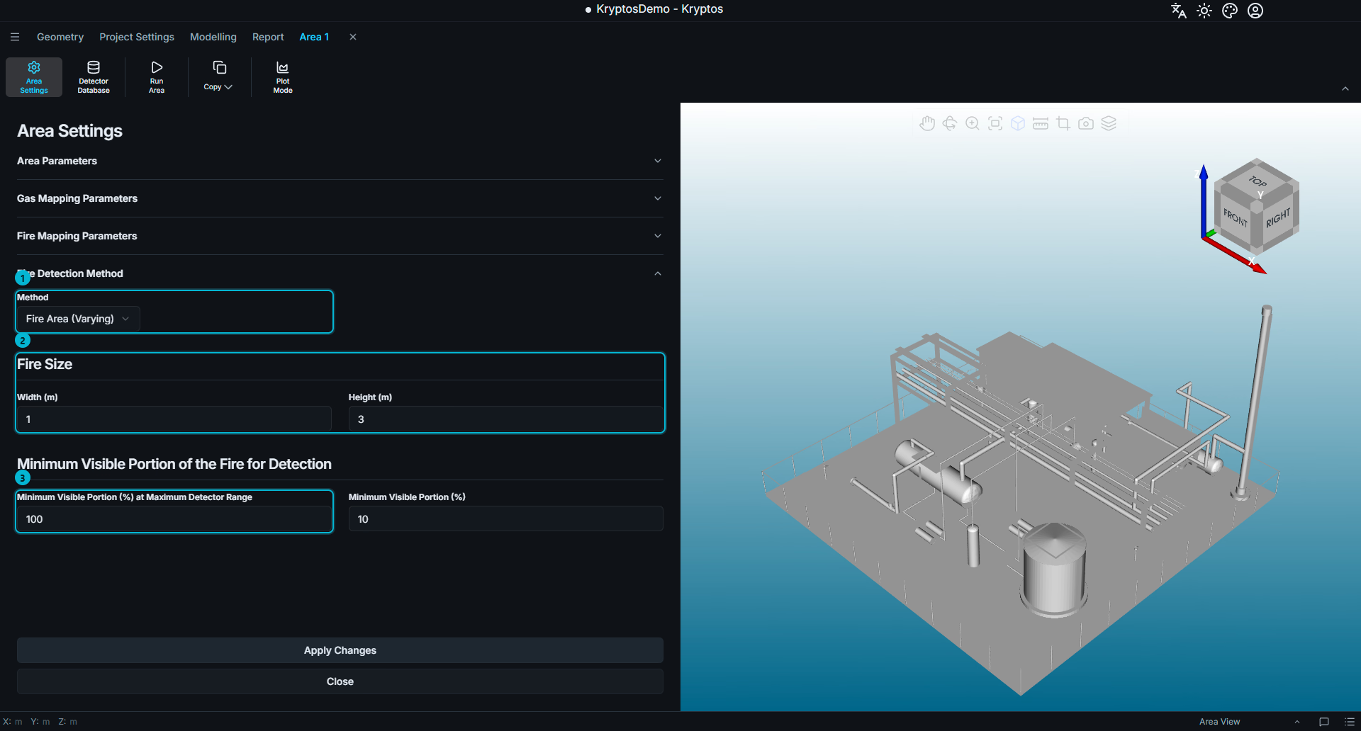
Method — defines the calculation method used by Kryptos to determine successful detection of a fire by a fire detector. For more details refer to Fire Calculation Methods.
Fire Size — defines a minimum fire size (as defined by the project's safety philosophy documents) that needs to be detected by a detector for the fire to be considered as "detected". You can provide this fire size in terms of width and height to Kryptos. This fire size is evaluated at each point in the Risk Grade. This parameter applies only to the fire-area methods. For more details refer to Fire Calculation Methods.
Minimum Visible Portion (%) at Maximum Detector Range — defines the minimum visible portion of the fire at the maximum detection range of the detector for the fire to be detected. This parameter applies only to the Fire Area (Varying) method.
Minimum Visible Portion (%) — defines the minimum visible portion of the fire (irrespective of distance between fire and detector) for the fire to be detected. This parameter applies only to both the Fire Area methods - Fixed and Varying.
Kryptos supports three fire detection methods:
| Calculation Method | Description |
|---|---|
| Point | This is equivalent to geographical coverage. The entire fire zone (area) that is inside a Risk Grade but outside the 3D geometry is divided into closely spaced points (using a spacing of 0.1 to 0.25m). Each point is considered covered only if it is visible to a detector by direct line of sight and within the range of that detector for the corresponding Risk Grade. For more details refer to Fire Calculation Methods. |
| Fire Area (Fixed) | This method assumes that a minimum fire size (as defined by the project's safety philosophy documents) needs to be detected by a detector for the fire to be considered as "detected". You can provide this fire size in terms of width and height to Kryptos. The required proportion of the fire area that must be visible to the detector remains constant in this method, regardless of the distance of the fire from the detector. The percentage portion is generally kept as 100% in this method. For more details refer to Fire Calculation Methods. |
| Fire Area (Varying) | This method is similar to the Fire Area (Fixed) method but with one key difference. The required visible proportion of the fire that needs to be visible to the detector varies with distance between the fire and the detector based on an inverse-square relationship. The closer the fire is to the detector, the smaller the visible portion of the fire needs to be for the detector to pick up sufficient radiation and detect the fire. For more details refer to Fire Calculation Methods. |
WARNING
Minimum Visible Portion cannot exceed Visible Portion at Maximum Range. Under the varying method, the required visible portion of fire changes with the distance between the fire and the detector. The minimum visibility sets a lower limit on this requirement at extremely short distances (e.g., 1m away from the detector). It must therefore not exceed the visible portion required at the maximum detection range. Kryptos will reject a value that violates this constraint.
WARNING
Changing any parameter under Fire Detection Method recalculates all fire configurations in the current area. Choose the appropriate method and configure its parameters before carrying out detailed fire mapping, as changing them later will trigger recalculation.
The three methods and their underlying calculation principles are explained in detail in Fire Calculation Methods.
Related
- Project Settings — configure the gas components and grades available to the project.
- Fire Detectors — understand field of view (FOV), curvature and detection range.
- Fire Calculation Methods — detailed explanation of the three fire detection methods.