Project Settings
Project Settings define the parameters that apply to the entire project rather than to an individual area. These include the project units, voting configurations, risk grades and their coverage targets, gas components, detector placement constraints, and automatic save settings.
It is recommended to configure these settings before you begin modelling.
The Project Settings Tab
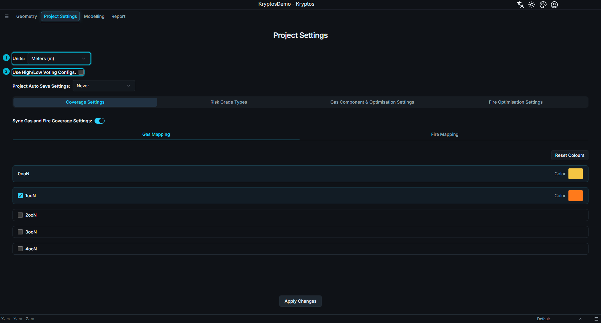
Three settings are located above the sub-tabs because they affect the details you will feed into the project settings.
Units — defines the unit of length used throughout the project. Coordinates, diameters, heights, and detection ranges are all entered and reported using this unit. Available options are metres, feet, inches, and millimetres. The default is metres.
Use High/Low Voting Configs — disabled by default. When enabled, a Voting Config column is added to Coverage Settings, allowing you to define the voting configuration you want for each voting level.
Project Auto Save Settings — defines how frequently the project is automatically saved. Auto Save can be set to 1 min, 10 min, 45 min, 1 hour, or Never.
The remaining settings are organised into four sub-tabs: Coverage Settings, Risk Grade Types, Gas Component & Optimisation Settings, and Fire Optimisation Settings. Changes are not applied immediately; click Save Changes at the bottom of the page to apply them.
WARNING
Auto Save does not pick up unsaved changes on this Project Settings page by itself. Click Save Changes first — once applied, those settings are saved as part of the project and are included the next time Auto Save runs.
WARNING
Set the project unit before you import any geometry. Changing it afterwards does not resize your model — it just relabels the same numbers with the new unit, so the geometry ends up the wrong size. If you need a different project unit, set it here first, then import your geometry.
WARNING
Auto Save is set to Never by default. In this mode, the project is saved only when you save it manually. For long modelling sessions, consider enabling Auto Save to reduce the risk of losing work.
Coverage Settings
Voting logic defines how many detectors must detect a location simultaneously for it to be considered covered. This tab allows you to enable the voting levels used by your assessment and define the colour used to represent each level. These settings are later also used in the coverage tables and Plots in the Modelling tab.
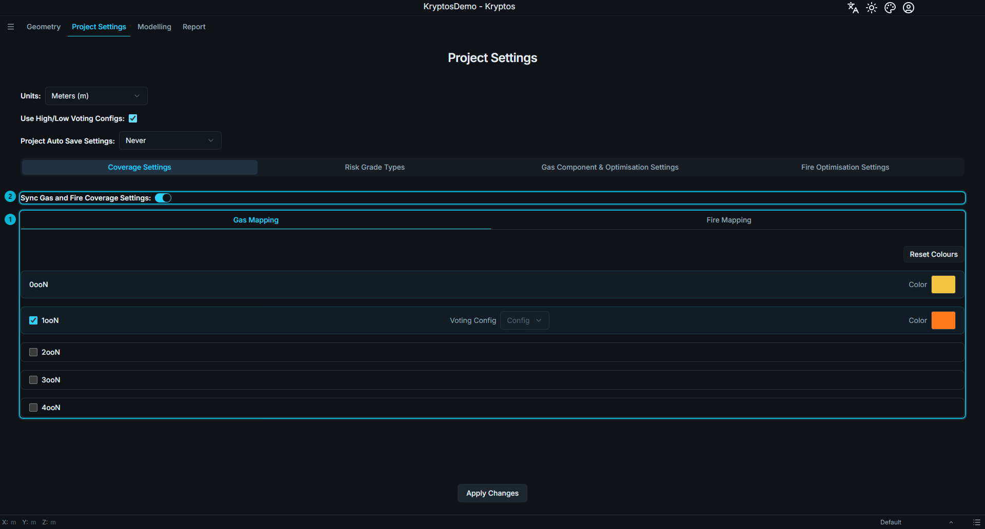
Voting logic rows — one row for each voting level, from 0ooN to 4ooN. Gas and fire have separate settings on their respective tabs.
Sync Gas and Fire Coverage Settings — synchronises the coverage settings between the Gas Mapping and Fire Mapping tabs, i.e., changing any settings in the gas tab automatically applies the same settings to the fire tab and vice versa.
The Voting Levels
| Level | Meaning |
|---|---|
| 0ooN | No detector covers the said location. This level is always enabled and cannot be disabled. |
| 1ooN | At least 1 detector (present amongst all detectors) covers the said location successfully. |
| 2ooN | At least 2 detector (present amongst all detectors) cover the said location successfully. |
| 3ooN | At least 3 detector (present amongst all detectors) cover the said location successfully. |
| 4ooN | At least 4 detector (present amongst all detectors) cover the said location successfully. |
Enable the voting levels required by your assessment. The colour assigned to each level is used to represent that level in the 3D and slice plots, and these colours are also used in exported reports.
Voting Configurations
When Use High/Low Voting Configs is enabled, each voting level can also be assigned a configuration consisting of High (H) and Low (L) values, with one letter corresponding to each vote.
For example:
- 1ooN —
LorH - 2ooN —
LL,LH, orHH - 3ooN — configurations containing three
L/Hvalues - 4ooN — configurations ranging from
LLLLtoHHHH
The following example illustrates what the voting configuration means for 1ooN and 2ooN. The same principle applies to 3ooN and 4ooN.
| Voting Configuration | Meaning |
|---|---|
| L (1ooN) | 1 detector alarming at Low Alarm Set Point or Low Level Set Point. |
| H (1ooN) | 1 detector alarming at High Alarm Set Point or High Level Set Point. |
| LL (2ooN) | Out of the 2 detectors raising an alarm, both the detectors are raising alarm at Low Level Set Point |
| LH (2ooN) | Out of the 2 detectors raising an alarm, one detector is raising alarm at Low Level Set Point and the other at High Level Set Point |
| HH (2ooN) | Out of the 2 detectors raising an alarm, both the detectors are raising alarm at High Level Set Point |
Voting configurations are designed so that the overall detection criterion becomes progressively more stringent as the voting level increases.
Here, H represents the High alarm threshold and L represents the Low alarm threshold. A voting configuration specifies which alarm threshold is considered for each detector participating in the voting logic.
The configuration at a higher voting level is constrained by the configuration at the level immediately below it. A higher voting level requires more detectors to alarm, and therefore its configuration should not be allowed to become disproportionately less stringent than the lower voting level.
Kryptos applies the following rule: a voting level may contain at most one more L than the voting level immediately below it. This prevents an abrupt change in alarm-threshold requirements as the voting level increases.
For example, if 1ooN is configured as H, the 2ooN configuration can be LH or HH, but LL is not permitted. An LL configuration would introduce two Low-threshold detectors at 2ooN when the preceding 1ooN level uses the High threshold. This would create an inconsistent progression in the detection criteria.
If 1ooN is configured as L, then 2ooN may be configured as LL, LH, or HH, because the 2ooN level is allowed to contain at most one additional L compared with the preceding 1ooN configuration.
The available configurations at each voting level are therefore determined by the configuration selected at the previous level. It is recommended to configure the voting levels sequentially, starting with 1ooN and progressing upwards to 4ooN.
| 1ooN Configuration | Available 2ooN Configurations |
|---|---|
H | LH, HH |
L | LL, LH, HH |
WARNING
Kryptos only hides the options that do not fit while you are choosing a configuration. It does not show an error when you click Save Changes. If you go back and change a lower voting level after choosing a higher one, the higher level keeps what you picked before, even if it no longer fits the rule above. Kryptos will still save it. After changing any voting level, check the levels above it and pick their configurations again.
Syncing Gas and Fire Coverage Settings
Gas and fire have separate voting configurations on their respective Gas Mapping and Fire Mapping tabs.
TIP
Most projects use the same voting logic for both gas and fire. Enable Sync Gas and Fire Coverage Settings to apply changes to both tabs simultaneously, so the configuration only needs to be set up once.
WARNING
Enabling synchronisation copies the gas coverage settings to the fire coverage settings. If the two configurations were previously different, the existing fire settings will be overwritten.
Risk Grade Types
Risk Grades classify the significance of a gas release or a fire at a given location. Coverage is reported for each risk grade, so the grade definitions form the basis of the overall coverage assessment.
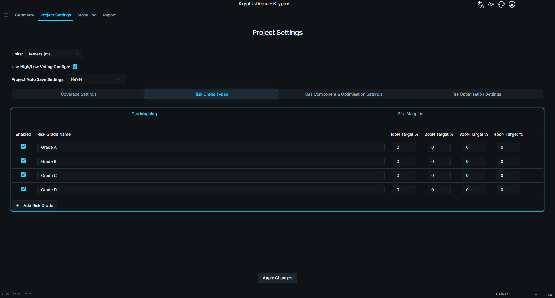
Gas and fire each have their own set of risk grades on separate tabs, under the Risk Grade Types tab. Both start with four risk grades — Grade A, Grade B, Grade C, and Grade D — all enabled.
For each grade, you can configure:
- Enabled — makes the risk grade available for use in the project.
- Risk Grade Name — the name you want to use for the risk grade throughout the application and in reports.
- 1ooN / 2ooN / 3ooN / 4ooN Target % — the target coverage percentage for each voting level, from 0 to 100%.
Add Risk Grade creates an additional custom risk grade. New risk grades are initially named Custom Grade 1, Custom Grade 2, and so on, until you rename them.
Coverage Targets
Coverage targets define what the optimiser works towards. When Kryptos automatically places detectors, it aims to achieve the target percentages specified here. Therefore, a grade with a target of 0% gives the optimiser no coverage target to achieve.
See 3D Gas Optimisation and 3D Fire Optimisation for further details on how to automatically let Kryptos optimise the number and location of the gas and fire detectors in a region.
WARNING
A risk grade that is in use — meaning it is referenced by one or more areas — cannot be deleted or disabled. Kryptos identifies the grade preventing the change. Remove the grade from all areas using it before attempting to disable or delete it.
Default grades (i.e., Grades A, B, C, D) cannot be deleted; they can only be disabled. The delete option is available only for custom grades that you have added.
WARNING
Deleting a risk grade also deletes all data associated with that risk grade. This includes detector diameters, fire detection ranges, and coverage results stored against the risk grade. This action cannot be undone.
Kryptos identifies the data that will be removed and asks for confirmation before deleting the risk grade.
Gas Component & Optimisation Settings
Gas Component & Optimisation Settings define which gases need to be detected in the project mapping and the height ranges within which the optimiser can place the respective gas detectors.
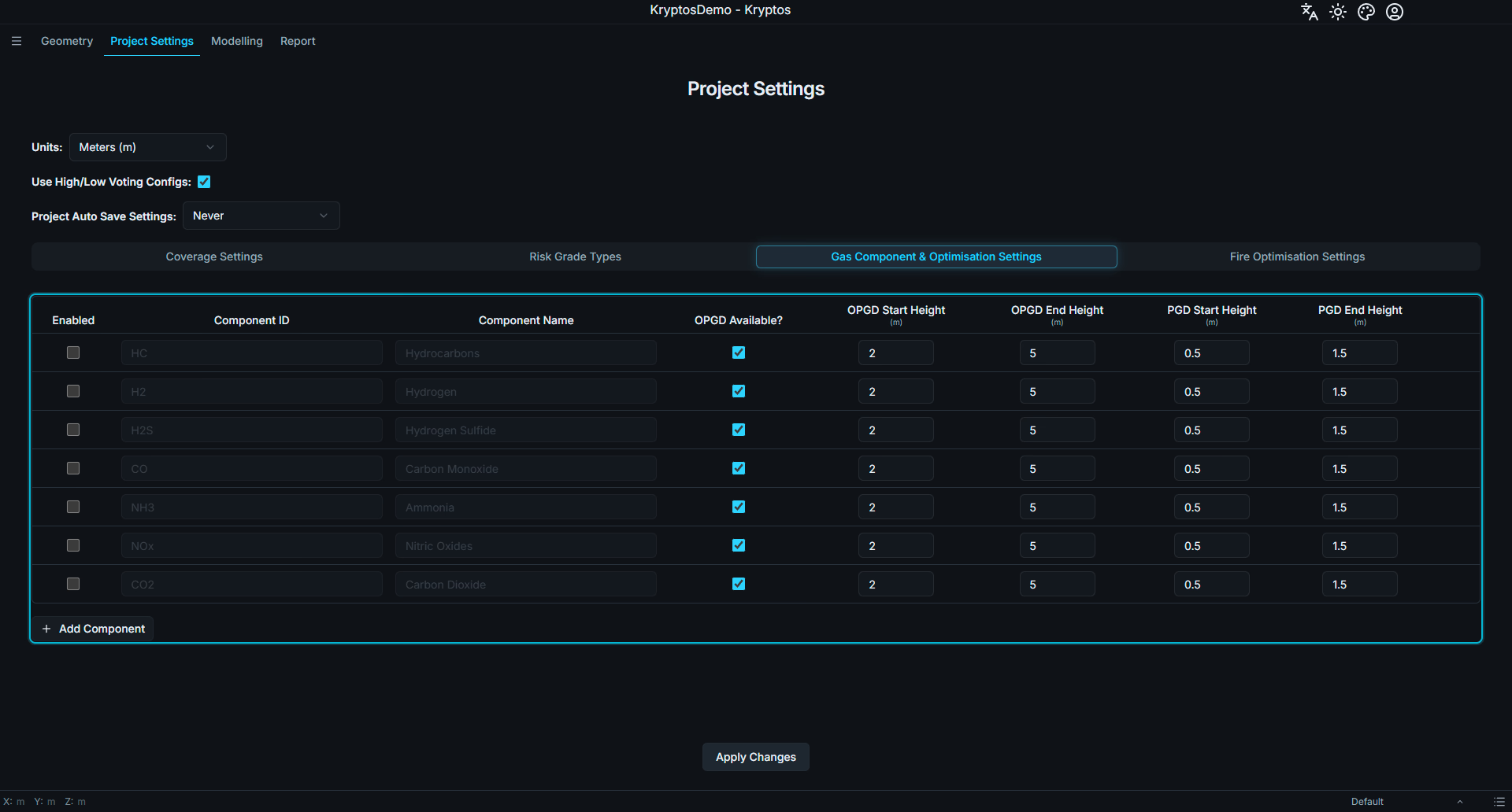
Kryptos provides seven pre-defined gas components:
- Hydrocarbons (HC)
- Hydrogen (H2)
- Hydrogen Sulfide (H2S)
- Carbon Monoxide (CO)
- Ammonia (NH3)
- Nitric Oxides (NOx)
- Carbon Dioxide (CO2)
Custom gas components can also be added. However, care must be taken to ensure that the Component ID is unique and different from the pre-defined gas components. Kryptos compares component IDs case-insensitively, so HC and hc are considered the same ID and cannot both be used.
None of the gas components is enabled by default. You need to enable the components required for the project assessment.
For each enabled component, placement constraints can be defined separately for the two gas detector types:
- OPGD Available? — specifies whether Open Path Gas Detectors (OPGD) are going to be used for the respective gas component in the current project. OPGDs are also known as Line of Sight detectors or LOS detectors in some countries.
- OPGD Start Height / End Height — defines the relative height range within which open path gas detectors may be placed above the nearest deck or ground level.
- PGD Start Height / End Height — defines the relative height range within which point gas detectors (PGD) may be placed above the nearest deck or ground level..
Start Height is the height above the nearest deck at which detector placement begins. End Height is the maximum height above the nearest deck at which detectors may be placed.
Together, these values define the vertical placement range within which the Kryptos Optimiser can position gas detectors. No detector is placed outside this range.
WARNING
Start Height must be less than or equal to End Height, and neither value may be negative.
New components start with a height range of 2 to 5 for open path gas detectors and 0.5 to 1.5 for point gas detectors, in project units. These suit many plants, but check them against yours. A range with no height (Start Height equal to End Height) leaves no space to place detectors.
TIP
Let's assume the Z co-ordinate of the deck is 5.5m above ground. Your project requirements state that the OPGDs should be placed 2 to 4m above deck level and PGDs between 0.5 to 1.5m above deck level. So you will need to set the start height of OPGD as 2m (not 5.5 + 2 =7.5m) and End Height as 4m (not 5.5+4=9.5m). Similarly, the Start and End Height of PGD should be entered as 0.5m and 1.5m respectively.
Fire Optimisation Settings
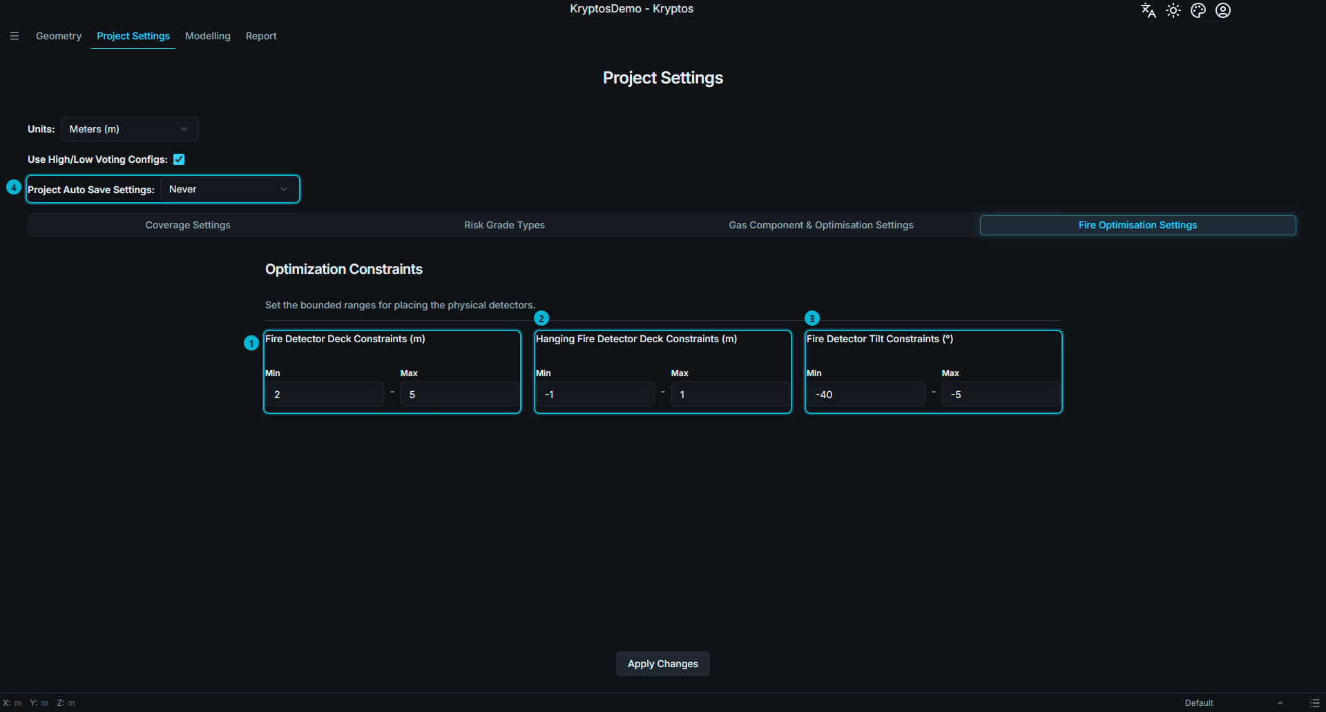
Fire Detector Deck Constraints — defines the relative height range above a deck, in project units, within which fire detectors may be placed. The default range is 2 to 5.
Hanging Fire Detector Deck Constraints — defines the corresponding height range for fire detectors suspended below a deck rather than mounted above it. The default range is −1 to 1. Negative values are expected for detectors positioned below the deck.
Fire Detector Tilt Constraints (°) — defines how far a fire detector may be tilted from horizontal. The default range is −40° to −5°, meaning the detector can be tilted downward by between 5° and 40°.
These settings constrain where the Kryptos Optimiser can place the fire detectors, in the same way that component height constraints limit gas detector placement. Wider ranges provide the optimiser with more possible detector locations, while narrower ranges may restrict its ability to achieve the specified coverage targets.
WARNING
For each constraint pair, Min must be less than or equal to Max. The settings cannot be saved until this condition is satisfied.
The default tilt values are both negative, which can make them easy to enter in the wrong order. −40° is the minimum and −5° is the maximum.
Related
- Signing In & Projects — creating the project these settings belong to.
- Geometry & Plot Plan — set the project unit before importing geometry.
- 3D Gas Optimisation — where component heights and coverage targets are used.